OrangePi Zero
Hardware
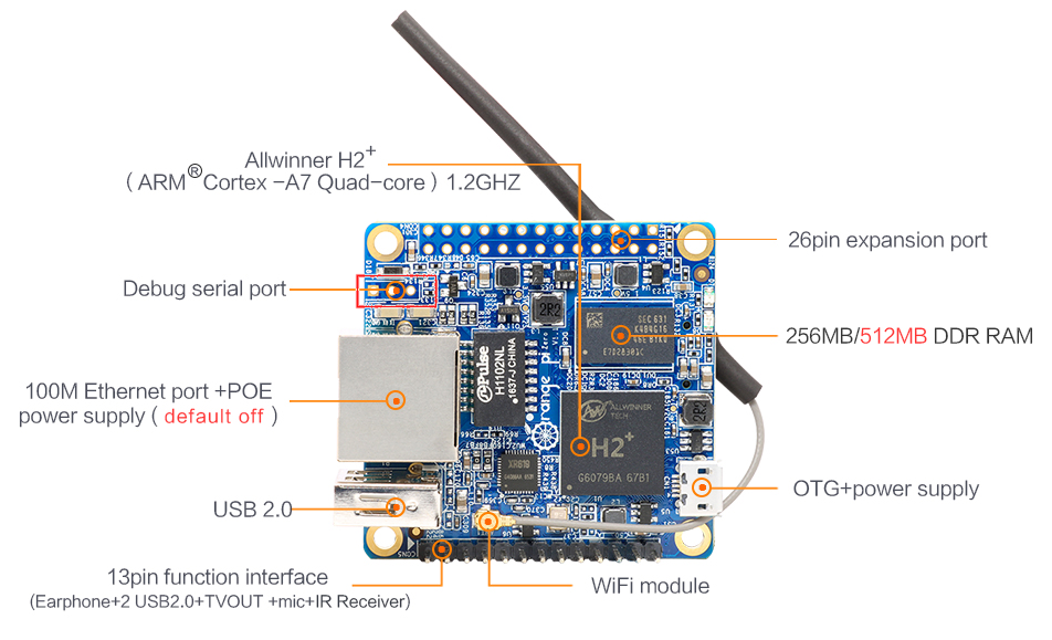
Orange Pi Zero v1.5
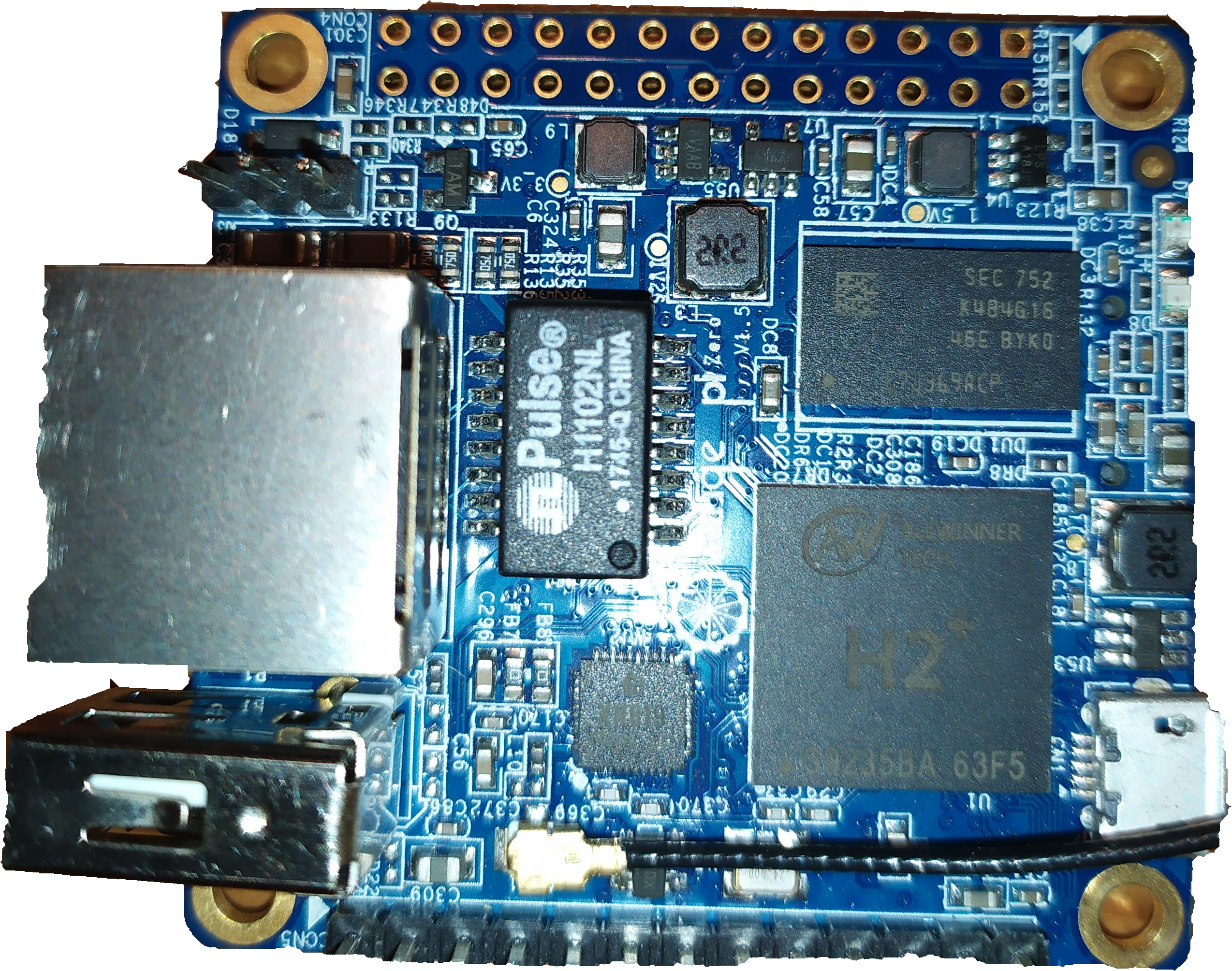
The OrangePi Zero is a Single Board Computer made by Shenzhen Xunlong Software CO., Limited, a company located in Shenzhen, Guangdong, China.
SoC
It is based on a downgraded version of the famous AllWinner H3 chip. This chip lacks Gigabit MAC and 4K HDMI output support), and is named H2+.
On the Zero, not all the features of the H2+ are hardwired. Thus, access to the camera, HDMI and Nand Flash are unavailable.
CPU
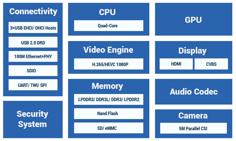
- The Allwinner H2+ is based around a quad-core Cortex™-A7 (32-bit) ARM CPU running at a dyamic clock speed - anywhere 480MHz to 1008MHz.
GPU
- The system uses a multi-Core Mali400 GPU, which has full support in mainline Linux kernels, and supports OpenGL ES 2.0
Display
Supports 1080P HDMI output with HDCPSupports HDMI CECSupports HDMI 30 function- Integrated CVBS
Supports simultaneous output of HDMI and CVBS
Memory
- Supports LPDDR2/ LPDDR3/ DDR3/ DDR3L SDRAM
- Supports 8-bit SLC/MLC/TLC/EF NANO with 64-bit ECC
- Supports SD/
eMMC/tSD/fSD/efSD
Video
- Supports multi-format 1080p@60fps video decoding, including H.265/HEVC, H.264 BP/MP/HP, VP8, MPEGl/2, MPEG4 SP/ASP GMC, H.263 including Sorenson Spark, WMV9/VC- l,JPEG/MJPEG, etc
- Supports H.264 1080p@30fps video encoding
Camera
Supports 8-bit YUV422 CMOS sensor interfaceSupports CCIR656 protocol for NTSC and PALSupports 5M pixel camera sensorSupports video capture solution up to 1080p@30fps
Pinout
1x13 Header
On the board itself, there is a first row of pins that reflect a few features of the SoC:
| 1x13 Header | |
|---|---|
| 1 | 5V |
| 2 | GND |
| 3 | USB-DM2 (combined to the pin #4, 5V and GND, this makes a USB port) |
| 4 | USB-DP2 |
| 5 | USB-DM3 (combined to the pin #6, 5V and GND, this makes a USB port) |
| 6 | USB-DP3 |
| 7 | LINEOUTR (audio output Right side) |
| 8 | LINEOUTL (audio output Left side) |
| 9 | TV-OUT (The default mode is PAL, with 720x576 resolution) |
| 10 | MIC-BIAS |
| 11 | MIC1P |
| 12 | MIC1N |
| 13 | CIR-RX (Infrared input) |
2x13 Header
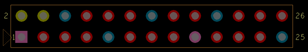
On the opposite side, we'll find an unpopulated series of holes. To connect more easily Dupont cables, one could solder a 2 x 13-pin header, angled, pitch 2.54 like this one:

| 2 × 13 Header | |||
|---|---|---|---|
| 1 | 3,3 V | 2 | 5V |
| 3 | PB21 TWI2-SDA / TWI0_SDA / PA12 / GPIO12 | 4 | 5V |
| 5 | PB20 TWI2-SCK / TWI0_SCK / PA11 / GPIO11 | 6 | GND |
| 7 | PI3 PWM1 / PA06 / GPIO6 | 8 | PH0 UART3_TX / UART1_TX / PG06 / GPIO198 |
| 9 | GND | 10 | PH1 UART3_RX / UART1_RX / PG07 / GPIO199 |
| 11 | PI19 UART2_RX / PA01 / GPIO1 | 12 | PH2 / SIM_CLK / PA_EINT7 / PA07 / GPIO7 |
| 13 | PI18 UART2_TX / PA00 / GPIO0 | 14 | GND |
| 15 | PI17 UART2_CTS / PA03 / GPIO3 | 16 | PH20 CAN_TX / TWI1-SDA / PA19 / GPIO19 |
| 17 | 3,3 V | 18 | PH21 CAN_RX / TWI1-SCK / PA18 / GPIO18 |
| 19 | PI12 SPI0_MOSI / PA15 / GPIO15 | 20 | GND |
| 21 | PI13 SPI0_MISO / PA16 / GPIO16 | 22 | PI16 UART2_RTS / UART2_RTS / PA02 / GPIO2 |
| 23 | PI11 SPI0_CLK / PA14 / GPIO14 | 24 | PI10 SPI0_CS0 / SPI1_CS / PA13 / GPIO13 |
| 25 | GND | 26 | PI14 SPI0_CS1 / SIM_DET/PA_EINT10 / PA10 / GPIO10 |
The numbers on the board are not the numbers that you will be able to use in your program.
As seen there, there is a formula that will help you to get the GPIO number when you have the pin number:
(Position of letter in alphabet - 1) * 32 + Pin number
For example, port PB12 would map to GPIO 44:
(2 - 1) * 32 + 12 = 44
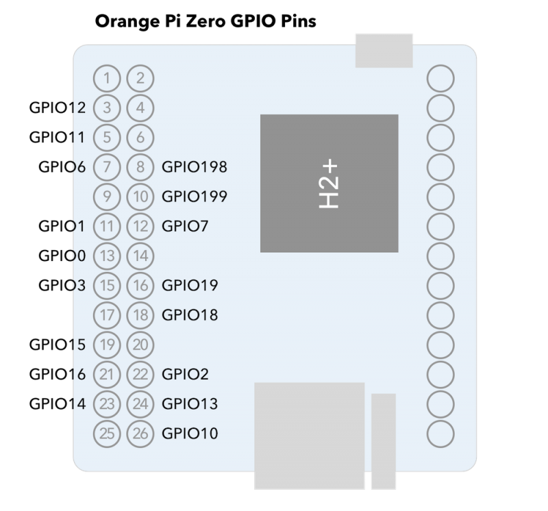
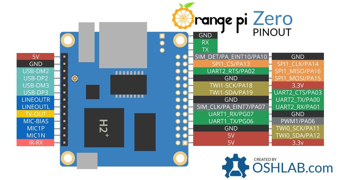
Here is a more detailed pinout:

Serial console
A UART or serial console will be a life-saver when anything goes wrong. The serial interface pins lies next to the Ethernet plug:
To connect to the board in case of problem, or if you don't have SSH installed, you need a TTL to USB converter like this one:
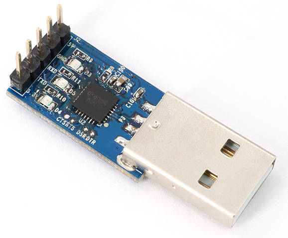
The RX an TX pins have to be connected to the TX and RX pins of the USB Serial converter respectively.
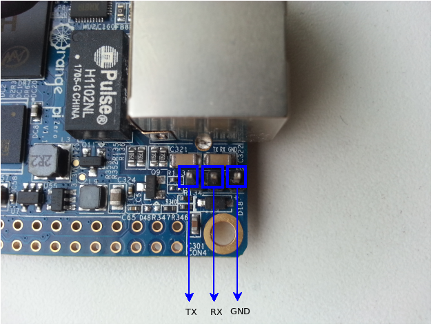
So TX goes to RX, RX goes to TX, GND goes to GND. We could also connect the converter to the pins 11 or 10 (RX, to connect to TX) and 13 or 8 (TX, to connect to RX).
Setting up the connection from another machine (Windows or Linux) will be detailed later in this document.
OrangePi documentation and source code
User manual
The user manual can be found there: https://mega.nz/#!K11y1YhY!aaKAcEvmyfaRHzoesHtjktgULdCDGyAW5FKweDWVSfo. The NAS user manual can be found there: http://www.orangepi.org/download/ORANGE_PI-Zero-NAS-V1_1_user_manual.pdf.
Mechanical schematics
The DXF drawing for the LTS version can be found there: http://www.orangepi.org/download/ORANGE_PI-Zero-V1_5_mechanical.dxf. The DXF drawing for the 1.1 version can be found there: http://www.orangepi.org/download/ORANGE_PI-Zero-V1_1_PCB-DWG.rar.
Electronic schematics
The electronic schematics for the LTS version can be found there: http://www.orangepi.org/download/ORANGE_PI-ZERO_V_1_5.pdf. The electronic schematics for the 1.11 version can be found there: http://www.orangepi.org/download/orange_pi-zero-v1_11.pdf.
Source code
The Android SDK source code can be found there: https://mega.nz/#F!r8tX2Lzb!OnL-ZKHmWGxnNN2uAc4GNQ. The Linux source code can be found there: https://github.com/orangepi-xunlong.
Linux
OrangePi's Debian
OrangePi supplies a Debian desktop version for the Zero LTS (supposedly the v1.5), the latest being from September 2019 (orangepi/orangepi). OrangePi supplies a Debian xfce desktop version for the Zero, the latest being from 2016-12-05 (root/orangepi). OrangePi supplies a Debian server version for the Zero, the latest being from 2016-12-01 (root/orangepi).
OrangePi's Ubuntu
OrangePi supplies a Ubuntu server version for the Zero, the latest being from 2016-11-24. (orangepi/orangepi) The Ubuntu Core they supply is from 2018-02-05. (orangepi/orangepi) The Lubuntu they supply is from 2016-11-25. (orangepi/orangepi)
Armbian
Armbian supplies Armbian Buster with mainline based kernel 5.3.y. Armbian supplies Armbian Bionic with mainline based kernel 5.3.y. They also supply other versions of Armbian, not all of them are supported: Bionic server, Buster server, Buster minimal, Disco server, Stretch server.
Others
OrangePi supplies a Raspbian server version for the Zero, the latest being from 2018-02-05 (orangepi/orangepi). OrangePi supplies an OpenWRT version for the Zero, the latest being from 2016-12-05 (root/orangepi).
Android
OrangePi Android
OrangePi supplies an Android KitKat (4.4) version for the Zero LTS, the latest being from August 2019. OrangePi supplies an Android version for the Zero, the latest being from 2018-3-15. OrangePi supplies an Android 7.0 version for the Zero, the latest being from 2018-3-15.
H3Droid
H3Droid is an Android built for Allwinner H3 and H2+ based devices. The universal installer can be downloaded there, or on this page: https://h3droid.com/download .
Connecting the Zero to the outside world
TVOUT
As seen there, if you want to get a correct image on the OrangePi Zero, as it is missing filter circuity from its Composite Output, the most important thing one needs to do is put a 50 ohm resistor between the signal and GND. It is RCA or "composite" signal: usually on a TV the yellow RCA connector is for composite signal, the white for left audio channel and the red for right audio channel. Use an RCA connector and get TVOUT from pin 9, left audio from pin 8, right audio from pin 7 and GROUND from where you want.
Then use "TV" or "AV" or "Audio Video" on your TV. One could also add the cheap Zero hat to get audio/tvout and more USB ports.
{.center}
Microphone
Once more, the cheapest and easiest way to connect a microphone to the OrangePi Zero is to use the OrangePi hat.
The other way is to connect a circuit like this one to the three available pins:
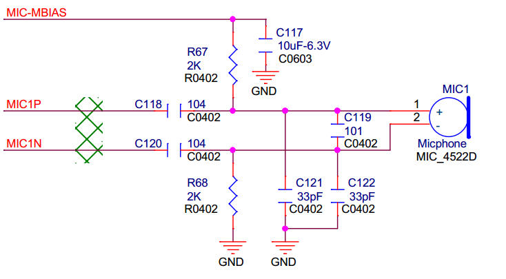
The MIC1N, MIC1P, MIC_MBIAS have to be connected to the respective pins of the 1x13 Header (12, 11, 10).
Sound out
Connect the pins #7 and #8 to a Jack cable, and you're done. If you don't get any sound from it, create a .asoundrc file in your home folder, and put this code in it:
pcm.!default {
  type hw
  card audiocodec
}
ctl.!default {
  type hw
  card audiocodec
}
InfraRed
The H2+ has an inbuilt IR controller, but no IR receiver on board. You can get a cheap hat that will give you more USB ports, TVOUT and an IR receiver, or go your own way and attach one to the GPIO.
Attach your own
Software
This micro howto is mostly inspired by codelectron.
On this board, and with Linux in general, infrared control is handled by project LIRC. LIRC allows to decode, and even send infrared signals for lots of commonly used infrared remote controls. The most important part of LIRC is the daemon lircd, which decodes infrared signal received by the device drivers. Il will then provide the information on a Unix socket. It will also accept commands for IR signals to be sent if the hardware supports it. The second daemon program is called lircmd. It will connect to lircd and translate the decoded IR signal to mouse movements.
cat /etc/armbian-release
BOARD=orangepizero
BOARD_NAME="Orange Pi Zero"
BOARDFAMILY=sun8i
BUILD_REPOSITORY_URL=https://github.com/armbian/rkbin
BUILD_REPOSITORY_COMMIT=cd0c2bb
DISTRIBUTION_CODENAME=buster
DISTRIBUTION_STATUS=supported
VERSION=19.11.3
LINUXFAMILY=sunxi
BRANCH=current
ARCH=arm
IMAGE_TYPE=stable
BOARD_TYPE=conf
INITRD_ARCH=arm
KERNEL_IMAGE_TYPE=Image
In the Armbian version mentioned above, the IR kernel module for Orange Pi is not loaded by default. CIR stands for Consumer Infra Red. First of all, we have to install cir support via armbian-config. System -> Hardware -> cir
{.center}
Once your machine has rebooted, check if the CIR kernel module is available.
lsmod |grep sunxi_cir
returns nothing. So we have to load the module manually:
modprobe sunxi_cir
After loading the module check if the device node is created and if that exist you can test the incoming IR signal.
ls /dev/lirc0
# if the above command runs and waits then press any key in your IR remote pointing it to the OPi IR Receiver
Temperature
Passive cooling
The H2+ chip can run pretty hot, especially on some versions (the infamous 1.4) so a heat sink is not a bad idea. The chip measures 14mmx14mm so any heat sink of this size could help maintaining a correct temperature.
One can glue the heat sink to the H2+ chip using “heat sink plaster”. This is a thermally conductive substance that hardens after some time. Another option is to use thermally conductive double sided adhesive tape. If you're thinking of an enclosure to keep dust out of your board, think twice, or upgrade to active cooling.
Active cooling
Another way of cooling the Zero is to use a fan. It's not such a good idea to plug a fan directly into the GPIO (be it PWM or not), as it could damage the board when slowing down. You need to have at least a Schottky diode or at least a resistor and a transistor to protect the GPIO, or you can go the full monty with a specific hat.